A Camera Monitor System (CMS) consists of a camera, an image processing pipeline, and a monitor for viewing the camera image. Examples include automotive side and rear view mirror replacement systems and medical endoscopes (where the doctor views the endoscope image on the monitor).
Although there are good reasons to test the components separately (this lets you find out where degradations occur), sometimes the complete system needs to be tested. for example, camera 1 output (shown below) may not be available. Testing the complete system requires a high-quality camera whose resolution is considerably better than that of the CMS camera and monitor. This is not difficult to achieve with modern mirrorless, DSLR, or industrial cameras with 12+ megapixels with good lenses.
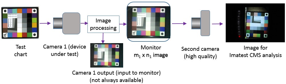 Camera Monitor System diagram showing second camera for testing
The key issues in performing this measurement are
- The second camera, used to acquire the monitor image, must have significantly better resolution than the original camera and monitor (device under test). Here are some reasonable criteria for “significantly better”.
- The height of the monitor image in the Camera 2 image should be at least 3X the original Camera 1 Image Height (1752 and 480 pixels, respectively, in the example below).
- The MTF50 in Cycles per Pixel (C/P) of Camera 2 (derived from an image of a high quality test chart) should be at least 5X the measured MTF in C/P of the complete CMS system. The measured CMS MTF in the example below is 0.03597 C/P. Any respectable camera (that isn’t defective) should have MTF50 in the range of ~0.2 to 0.4 C/P, so this criterion is usually easy to meet. You can do a quick and easy subjective test to see if the Camera 2 image is good enough. Look at the edge of the screen (any details near the screen image not from the screen image itself). They should be much sharper than the screen image. Here is an example, where the edge of the screen, on the left, is clearly much sharper than the detail in the image.
 Camera 2 image, where the edge of the screen is subjectively much sharper than the screen image.
This can be accomplished with 12+ megapixel cameras such as
-
- mirrorless cameras with Micro Four-Thirds or APS-C-sized sensors, available from Sony, Panasonic, Fuji, or Olympus,
- DSLR cameras with APS-C-sized sensors from Nikon, Canon, and others. (DSLRs should be mounted carefully to minimize degradations due to mirror slap.), or
- Industrial cameras.
We recommend good quality prime lenses (macro lenses usually work very well) stopped down to around f/8 for good sharpness and depth of field. High-end full-frame cameras are usually overkill for this purpose.
- The first camera (device under test) has its own signal processing, which typically includes noise reduction and sharpening. The monitor driver may have additional signal processing, which often includes sharpening (beyond the sharpening in the camera). In most cases the image of the monitor taken with the second camera will have lower MTF (when properly scaled for comparison) than the image from the first camera, though there is a small chance that sharpening in the monitor driver may cause it to be slightly higher.
- Units for measuring MTF must be consistent. Getting the units right is tricky. We will describe the procedure below.
|
Units are discussed in the Sharpness – Spatial Frequency Units.Typical units for measuring MTF are Line Widths (or Pairs) per Picture Height (LW/PH or LP/PH). These units describe the total detail the camera can convey. These are the units used to analyze the image from the first camera, as shown on the right. Picture Height typically refers to the smaller dimension of the image, in this case 480 pixels (for the VGA image). This image is representative of the output of camera 1. It fills the monitor. (We are not sure it is the same image photographed in the CMS monitor, below.) The image is the Rezchecker chart, which is photographed in portrait format (higher than it is wide) when colors are to be analyzed. This is rather unusual— most test charts are designed to be photographed in landscape format (wider than high). |
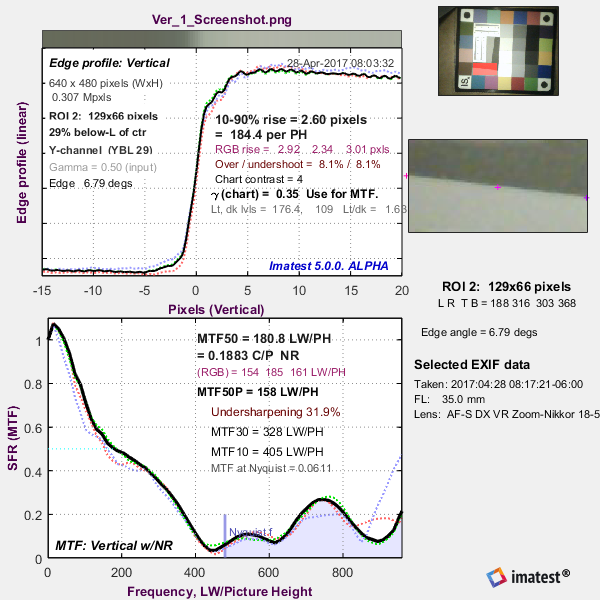 Analysis of theCamera 1 output image (in LW/PH) Analysis of theCamera 1 output image (in LW/PH) |
|
The pixel count and framing of the second camera is completely different. In order to obtain consistent units, we need to measure the height of the screen in the second image— corresponding to the height of the Camera 1 output image (which fills the entire monitor screen). The analysis of the CMS monitor image, photographed by Camera 2 (a 12.2 megapixel Nikon D90 DSLR) and shown on the right, is a bit confusing because the chart has been rotated 90 degrees from the above image. The key information you need to obtain is the equivalent height of the monitor (in pixels) in the image, which can be determined in many ways. |
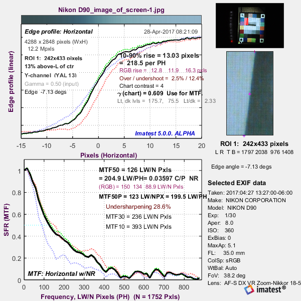 Analysis of the Camera 2 image (in LW/1752 pixels, Analysis of the Camera 2 image (in LW/1752 pixels,which is equivalent to LW/PH in Camera 1). |
|
Measuring the equivalent monitor height in the Camera 2 output image (used to analyze the CMS) You can measure it in a number of ways. We illustrate it with the Imatest File Statistics/Viewer utility, which can be called from the Utilities dropdown menu in the Imatest main window or from the Rescharts, Multicharts, or Uniformity Interactive windows. 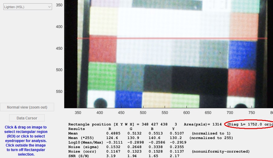 Crop of Image Statistics/Viewer utility window Open the Image Statistics/Viewer utility, then open the image file. Identify the top and bottom of the monitor image, and if necessary, crop the image (by dragging and dropping the mouse) so if comes close to filling the image. It’s not difficult, but in this case the final image has been rotated 90 degrees. Push the Rectangle analysis button on the left (not shown above), then drag and drop the mouse to select the area corresponding to the monitor height (shown in red above as a very narrow horizontal rectangle— almost a line). The number of pixels (1752) is shown on the right below the image. Note that this number always references the original image (not downsampled). Note also that it is more than 3X the Picture Height of the Camera 1 image (480 pixels), which is entirely adequate. To turn off Rectangle analysis, click outside the image. (This will leave the last results displayed.) For the camera 2 image, 1752 pixels is equivalent to the 480 pixel height of the Camera 1 image, i.e., equivalent to the monitor height. MTF units of Line Widths per 1752 pixels are equivalent to units of LW/PH (Line Widths per Picture Height) in the Camera 1 image, i.e., the monitor. |
![]() To analyze the Camera 2 image in the desired units, use the MTF plot units and Picture Ht (Pxls) selection shown on the right for the SFR module, but available for all MTF measurements. This selection was used for the Edge/MTF analysis of the Camera 2 image shown above, which has frequency units of LW/N pixels (PH) (N = 1752 pixels). This is equivalent to Line Width/monitor height, i.e., Results with these units are directly comparable to results in LW/PH in the Camera 1 results (above). They are also equivalent to Line Widths per Monitor Height, and hence are good units for measuring monitor sharpness.
To analyze the Camera 2 image in the desired units, use the MTF plot units and Picture Ht (Pxls) selection shown on the right for the SFR module, but available for all MTF measurements. This selection was used for the Edge/MTF analysis of the Camera 2 image shown above, which has frequency units of LW/N pixels (PH) (N = 1752 pixels). This is equivalent to Line Width/monitor height, i.e., Results with these units are directly comparable to results in LW/PH in the Camera 1 results (above). They are also equivalent to Line Widths per Monitor Height, and hence are good units for measuring monitor sharpness.
We have found the sharpness units in the ISO-16505 standard for Automotive Mirror Replacement / Camera Monitor Systems to be extremely confusing. We recommend replacing them with units derived from the calculations on this page.
See also
ISO 16505 — Road Vehicles — Camera Monitor Systems
Display (monitor) sharpness — detailed description of an important aspect of testing Camera Monitor Systems