Deprecated in Current Release
| Requirements | Software operation | Defining Calibration Tasks | Definitions and Theory |
|---|---|---|---|
Starting the Geometric Calibrator
The calibrator may be accessed by clicking the “Geometric Calibrator” button in the Imatest Master main window or clicking the “Interactive/Post” menu and selecting “Geometric Calibrator”
Geometric Calibrator Main Window
From the main window you can create a Calibration Task, run the module to produce a calibration, and view the results.
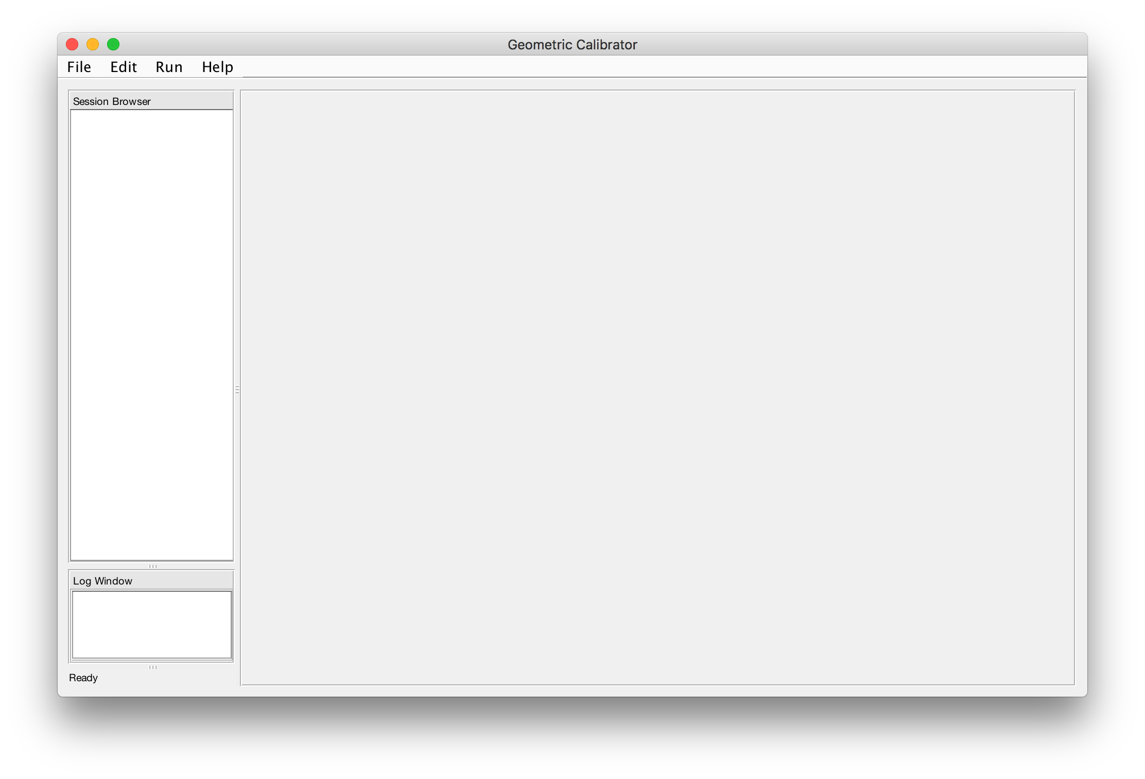
A previously-created Calibration Task may be loaded using the File → Open menu selection. Otherwise, one must be created.
Defining a Calibration Task
From the main window, select File → New Session. This brings up the Calibration Task editor, where you describe the devices to be calibrated, the test setup, and associate image files with metadata about the specific captures.
There are two major pieces of information that a Calibration Task contains:
- A System definition, that defines what devices to calibrate
- A set of Test Captures, which define what evidence to use to calibrate the devices
When you have finished defining a Calibration Task, the created components will appear in the Browser on the left and can be edited from there.
Defining a System
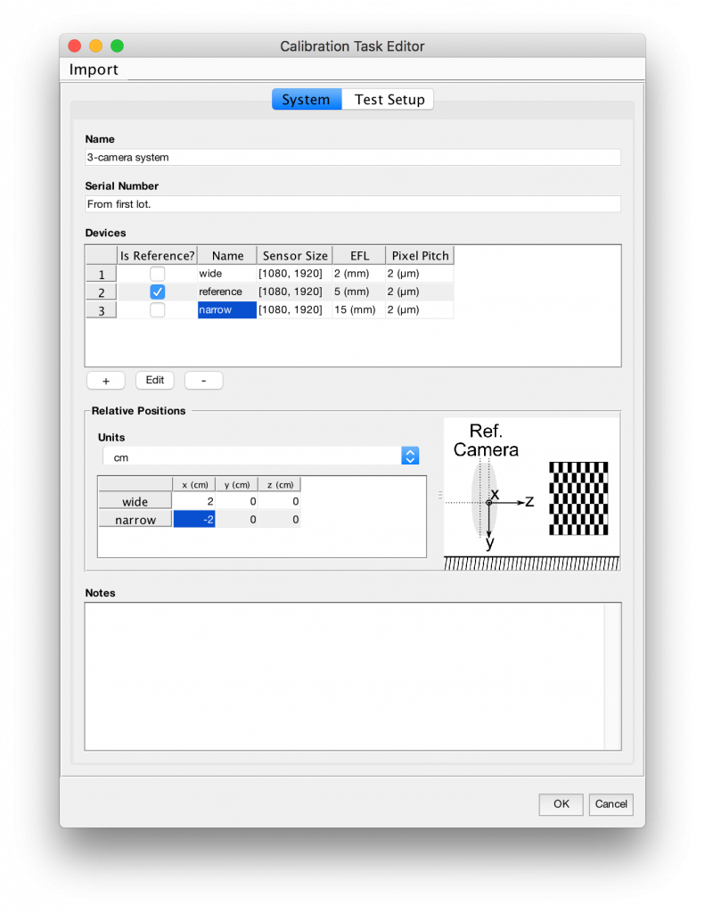
A System is defined from the System tab of the Calibration Task Editor. It represents the model of a rig of camera devices (which also includes the case of a single camera).
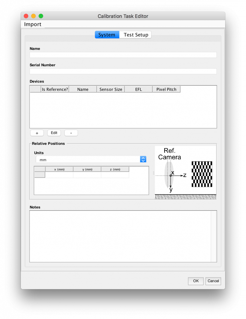
You may optionally supply a serial number and/or name for the system to tie the supplied model definition to a specific instance (i.e., a physical device).
Importing a System
You may optionally import a previously-created System definition from a JSON-encoded .device-system file.
Defining a Device
Click the plus under the Devices Table to bring up the Device editor and add a Device (camera) to the system.
Sensor size and pixel pitch values are required, as well as calibration parameters EFL and distortion of the Device. These latter parameters should be provided as the nominal values from spec, and they will be estimated and refined during calibration.
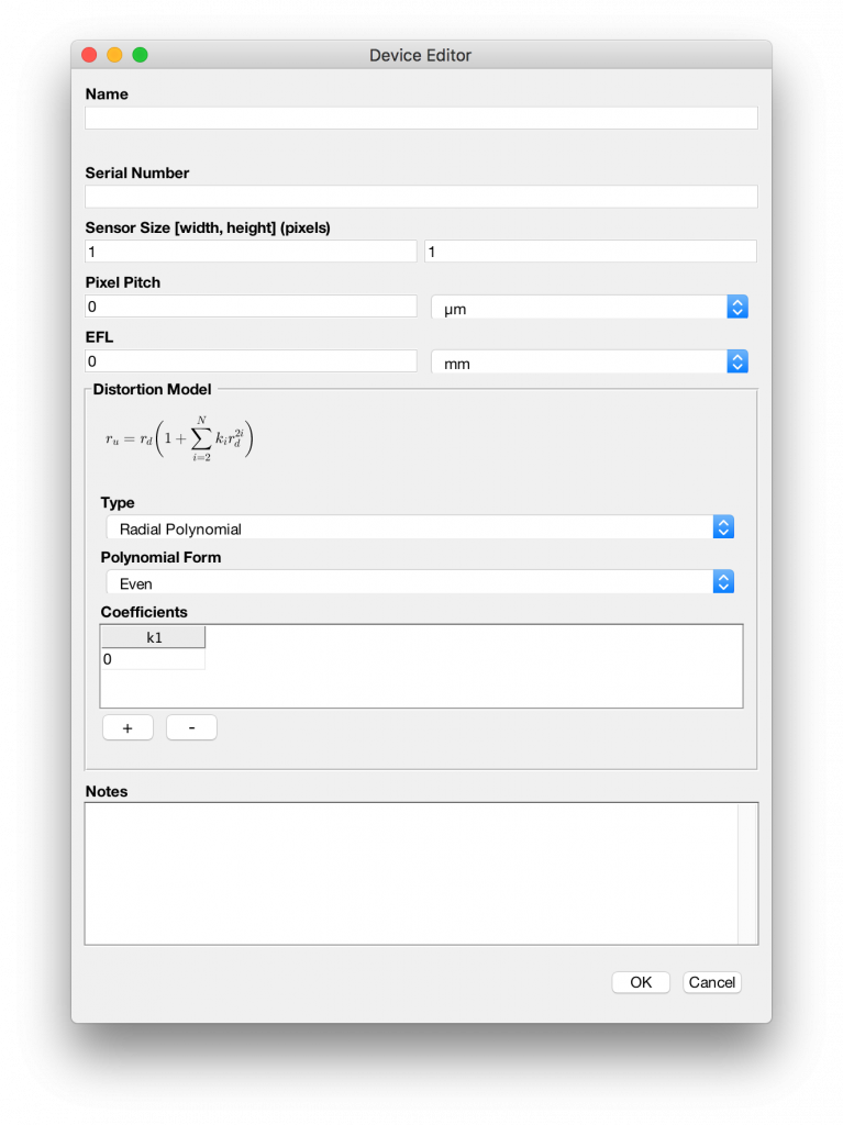
Name, serial number, and notes fields are optional.
When finished, press OK and add any additional devices in the system.
Defining Relative Device Locations
Select one of the Devices as a reference in the Devices table of the System tab. Other Devices need to have their positioning relative to this device entered (often called extrinsics). These values should be entered as a pose description.
The nominal positioning values should be entered, and these may be estimated and refined during calibration.
Defining the Test Captures
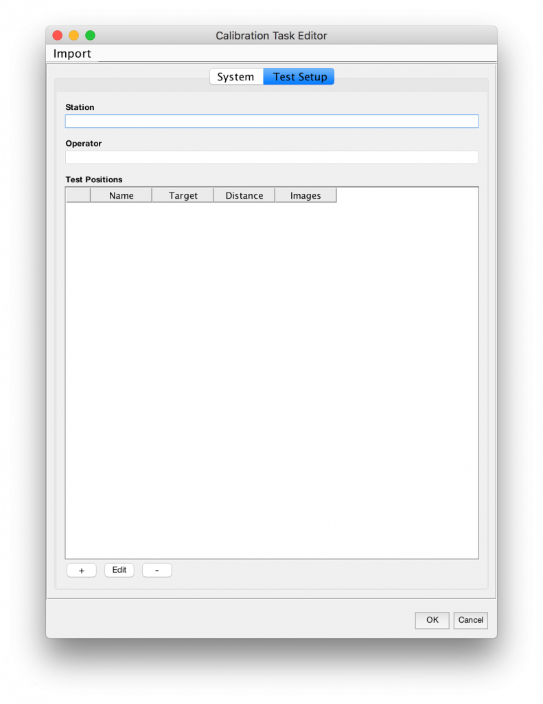
The test setup is defined by a target being viewed at a set of different test positions (also called Test Captures). Each such position is added as an entry in the Test Positions table using the ‘+‘ button.
Optionally enter the test station name and operator.
Add a Target
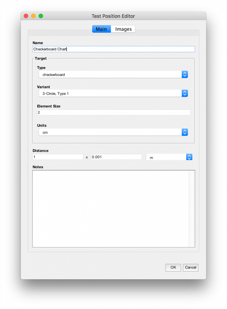
From the Main tab of the Test Position Editor, enter the information about the calibration target.
Also enter the distance from the test target origin to the reference device. A measurement error estimate must be included.
Add Images as Evidence
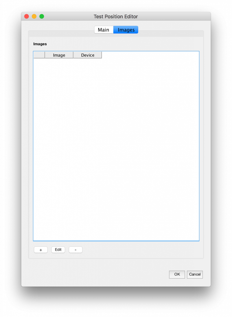
For each Test Capture, add a list of Test Image entries corresponding to images captured at this test position in the Images tab.
Use the ‘+‘ button to add Test Images. Each Test Capture should have an image from at least one Device defined in the System, but it is not required that every Device have an image at every capture position.
For each image that was captured at this test position, add an image using the Test Image Editor.
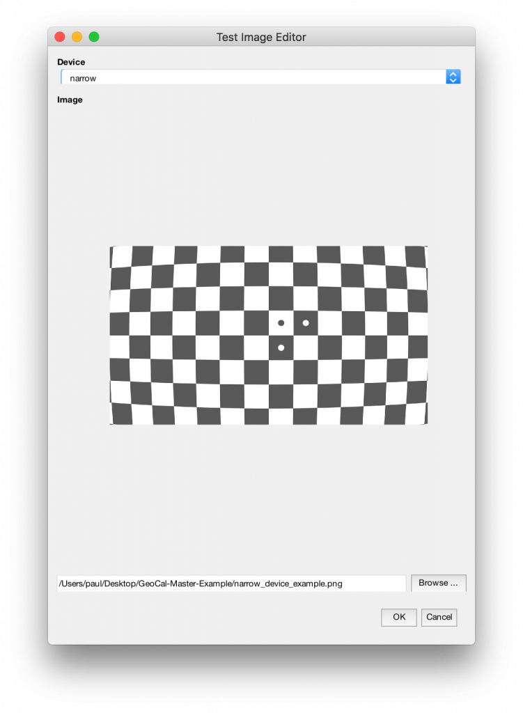
From the dropdown, select the Device that took the image. Enter the path to the image file, or press ‘Browse…’ to select it from a file browser.
Performing a Calibration
Once a Calibration Task has been defined on a System and set of Test Captures, the module can be run to produce a calibration on the System.
Select Run → Current Tab from the Geometric Calibrator Main Window. Some status output will display to the Log Window.
When the calibration is complete results will be displayed and a data JSON output will be produced in the chosen location.
Settings
The settings are edited from the Geometric Calibrator Main Window by selecting Edit → Settings.
Saving and Loading a Calibration Task
From the Geometric Calibrator Main Window, select File → Save to save the calibration task as a JSON-encoded .calibration-task file. This


