Running Rescharts slanted-edge modules
(Interactive and Auto mode settings)
Imatest Rescharts slanted edge modules— SFRplus, eSFR ISO, SFRreg, and Checkerboard— perform highly automated measurements of several key image quality factors using specially-designed test charts. This document shows how to run these modules in Rescharts and how to save settings for automated runs.
Four introductory pages — SFRplus, eSFR ISO, SFRreg, and Checkerboard — describe each module and explain how to obtain and photograph the chart.
Rescharts Results Part 3 and Part 4 illustrate the results.
Selecting files – Setup window – ROI selection & analysis – Edge ID files – Speeding up runs
More settings window – Secondary readout – Settings area – Gamma
Gamma from chart contrast ratio – Auto mode window – Warnings – Clipping – Summary
|
This page combines instructions for the four Rescharts slanted-edge modules In many cases we will use SFRplus as an example. The other module may be substituted. |
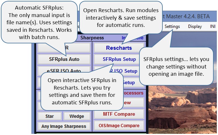 Open Imatest by double-clicking the Imatest icon
 ![]() on
on
- the Desktop,
- the Windows Start menu,
- the Imatest folder (typically C:Program files\Imatest\Master\ in English language Windows installations).
SFRplus, eSFR ISO, SFRreg, and Checkerboard operate in two modes:
- interactive/setup (in Rescharts) and
- Automatic (batch-capable).
Since Automatic runs for each module use settings from interactive/setup runs, an interactive/setup run should always be run first.
The following instructions apply to all Rescharts slanted-edge modules.
To start an interactive/setup run, press or , [module], where [module] is SFRplus, eSFR ISO, SFRreg, or Checkerboard. opens a dialog box for reading an image file for the selected module. is more general; it lets you open any Rescharts module.
Either of these buttons allows you to analyze an image for the chosen module, examine detailed results interactively, and save settings for the highly automated , , , or runs (or the even more automated Imatest IT versions). The module should be run interactively at least once prior to the first run. Settings can also be updated by pressing Settings, [module] Auto settings from the Imatest main window.
Selecting file(s)
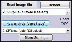 The portion of the Rescharts window used for opening files is shown on the right. You can open a file by clicking on if the correct chart type is displayed, or by selecting the required Chart type. One or more files may be selected, as shown below. If you select multiple files, they can be combined (averaged), and you’ll be given the option of saving the combined file.
If the folder contains meaningless camera-generated file names such as IMG_3734.jpg, IMG_3735.jpg, etc., you can change them to meaningful names that include focal length, aperture, etc., with the Rename Files utility, which takes advantage of EXIF data stored in each file.
The folder saved from the previous run appears in the Look in: box on the top. You are free to change it. The file name from the previous run is displayed at the bottom. You can open a single file by simply double-clicking on it. You can select multiple files for combined runs (for Interactive or Auto runs) or for batch runs (for Auto runs-only) by the usual Windows techniques: control-click to add a file; shift-click to select a block of files. Then click . Three image files are highlighted. Large files can take several seconds to load.
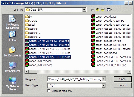
File selection
| Multiple file selection Several files can be selected in Imatest Master using standard Windows techniques (shift-click or control-click). For interactive (Rescharts) runs, files can be combined to reduce noise or (in some instances) observe the effects of camera shake or image stabilization. For runs, you can run large batches of images. The multi-image dialog box gives you the option of saving the combined file, which will have the same name as the first selected file with _comb_n appended, where n is the number of files combined. |
| RAW files Imatest can analyze raw files from cameras (using dcraw) or from development systems (using Generalized Read Raw). The files can be demosaiced or Bayer raw: standard files (TIFF, etc.) that contain undemosaiced data. Undemosaiced files are infrequently useful for measuring MTF because the pixel spacing in each of the four image planes is twice that of the image as a whole; hence MTF is lower than for demosaiced files. But Lateral Chromatic Aberration can be severely distorted by demosaicing, and is best measured in Bayer RAW files (and corrected during RAW conversion). Details of RAW files can be found here |
Setup window
When the file (or files) have been opened, the Setup window, shown below, appears. This window allows you to select groups of regions (ROIs; shown as violet rectangles) for analysis. It also lets you select the size of the regions, whether to analyze vertical or horizontal edges, and much more. Pressing on the left opens the SFRplus More settings, which allows you to select additional settings that affect the calculations and display. Pressing lets you select the output figures and files (for SFRplus auto mode runs). The light yellow-orange rectangles are for calculating the Color/lightness uniformity profiles.
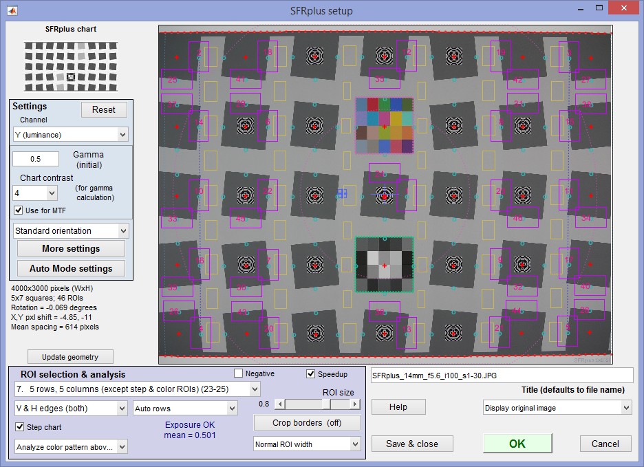 SFRplus setup window; 46 regions (23H + 23V) selected for analysis
| Setup window Settings relevant to speedup are shown with red background. |
||||||||||||||||||||||||||||||||||||||||||||||
| Settings area (upper-left) | ||||||||||||||||||||||||||||||||||||||||||||||
| Channel |
Select channel to analyze: R, G, B, Y, R-only, G-only, B-only, Y-only, Mean, Mean-only. (Y is the Luminance channel: normally recommended). Settings 1-4 and 9 (R, G, B, Y, and mean) analyze all channels, but emphasize (and display summary metrics for) the selected channel. Settings5-8 and 10 analyze the selected channel-only. Selecting one channel-only can significantly speed up calculations. The Luminance (Y) channel, which corresponds to human perception, is defined as Y = 0.2126*R + 0.7152*G + 0.0722*B. The Options III window lets you select between this recommended value and an older (NTSC-based) value of 0.3*R + 059*G + 0.11*B. |
|||||||||||||||||||||||||||||||||||||||||||||
| Gamma | Assumed Gamma (contrast) of the chart. Has a small effect on the MTF results. Default is 0.5. Overwritten (only used for an approximate initial estimate) if the Use for MTF checkbox (below Chart contrast) is checked. Described in more detail below. |
|||||||||||||||||||||||||||||||||||||||||||||
| Chart contrast (for gamma calc.) |
Chart edge contrast (for the contrasty squares in older charts that have 10:1 and 2:1 contrast edges). Can be used to estimate gamma from the image for charts with contrast ≤ 10. | |||||||||||||||||||||||||||||||||||||||||||||
| Use for MTF | (Checkbox) When checked, gamma derived from individual slanted-edges on the chart is used for MTF calculations. This may result in a small improvement in accuracy. Calculation details below. | |||||||||||||||||||||||||||||||||||||||||||||
| Orientation | [SFRplus, eSFR ISO] Selections are Standard orientation [default], Mirror (H or V), Rotate (180, 90 CCW, 90 CW) Applies to the next read. | |||||||||||||||||||||||||||||||||||||||||||||
| Reg mark detection | [SFRreg-only] Selections are Autodetect # SFRreg or 1-30 regmarks. Entering the number may be somewhat faster and more accurate in some situations, but isn’t generally necessary. | |||||||||||||||||||||||||||||||||||||||||||||
| Open the More settings window, shown below. | ||||||||||||||||||||||||||||||||||||||||||||||
| Open the Auto mode settings window, shown below, for controlling Rescharts runs. | ||||||||||||||||||||||||||||||||||||||||||||||
| ROI Selection & analysis area (lower-left) | ||||||||||||||||||||||||||||||||||||||||||||||
|
Region selection Note that selections are different for each module |
Select the regions (ROIs) to analyze. Choices below. The number of regions is in parentheses. This is a particularly important setting. We encourage users to become familiar with the settings below. Note that the squares above and below the middle square are usually not selected for analysis; they are reserved for other purposes (step chart, color chart, and/or focusing pattern). At least 9 regions are required for 3D plots (but 13+ are recommended).
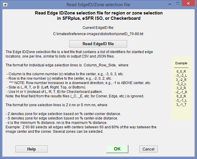
An Edge ID/Zone selection file contains a list of identifiers for slanted edge ROI locations or selection zones, one per line, similar to lists in CSV and JSON output files. There are two types of data line: for individual ROIs and for ROI selection zones. It allows you to freely select edges or zones. This window opens when you click Click Read EdgeID file to read the file. Then click OK. Individual edge ROI selection lines: The format is Column_Row_Side, where
Example: -2_1_L selects the left edge of the square two columns left of center and one row below center. Zone selection lines: The format is Z ii nn or S ii nn, where
Example: Z 60 80 selects all edges with centers between 60 and 80% of the way between the image center and the corner. Several zones can be selected. Other selections may be added on user request. |
|||||||||||||||||||||||||||||||||||||||||||||
| Vertical, Horizontal edges (or both) | Chooses between Vertical and Horizontal edges (or both). Often Vertical, but Horizontal is also frequently useful. Use both for Lens-style MTF plots. For 3D plots it’s best to plot Horizontal or Vertical-only. |
|||||||||||||||||||||||||||||||||||||||||||||
| Step chart (checkbox) | [SFRplus, eSFR ISO] (√) Perform step chart analysis. Should be unchecked for charts that do not include the step chart (such as transmissive chrome-on-glass charts). Checked by default. | |||||||||||||||||||||||||||||||||||||||||||||
| Full/Reduced image for detection | [Checkerboard] Use full, 1/2X, or 1/3X image for detecting checkerboard corners. Full is the normal default, but a reduced image may speed up detection, which can be slow. | |||||||||||||||||||||||||||||||||||||||||||||
| Color chart | [SFRplus, eSFR ISO] Perform color analysis for charts with a color pattern or (SFRplus-only) analyze the square above the center. Be sure the correct Color reference (file name) and Color space has been entered in the Settings region of the More settings window. Unchecked by default. | |||||||||||||||||||||||||||||||||||||||||||||
| Crop function (Normal/Exclude) | [SFRreg-only] Selects the crop function. Normal crop means analyze the crop area. Exclude crop from detection means exclude the crop area— analyze only outside the crop. | |||||||||||||||||||||||||||||||||||||||||||||
| Rows (Auto or number) |
[SFRplus-only] The number of rows of squares in the chart (between the top and bottom bars) or Auto for automatic row detection (the default). In rare cases Automatic row detection may fail and the actual number of rows (4, 5, or 7) may work better. If there are no bars, select Auto- no bars, and the regions will be similar to what you would get with the bars at the top and bottom of the image. Distortion and Field of View won’t be calculated. |
|||||||||||||||||||||||||||||||||||||||||||||
| Extra reg marks | [eSFR ISO-only] The number of extra registration marks outside the eSFR ISO chart to be used for MTF analysis. Default is 0. | |||||||||||||||||||||||||||||||||||||||||||||
| Negative | [SFRplus-only] (√) Check this box for negative images (light squares on dark background). |
|||||||||||||||||||||||||||||||||||||||||||||
| Speedup (checkbox) | (√) Speed up the run by eliminating some calculations that many users don’t require, including SQF/Acutance, noise statistics and histograms. Recommended. | |||||||||||||||||||||||||||||||||||||||||||||
| ROI size | Slider that determines the size of the ROI. Use the largest value that keeps a save distance from edges of squares and top and bottom bars. May need to be reduced where barel distortion is severe. | |||||||||||||||||||||||||||||||||||||||||||||
| Allows borders to be cropped to remove interfering patterns that might otherwise be included in the image. This button is tinted pink whenever the image is cropped. | ||||||||||||||||||||||||||||||||||||||||||||||
| ROI width (below ROI size slider) and Extra smoothing |
Width of ROI selection. Available settings: Normal, Wider, Widest, without or with Extra smoothing. Use Normal width for standard rectangular ROIs. Choose Wider or Widest for fuzzy edges, for enhanced noise analysis, or for more extended low frequency response. Use one of the Extra smoothing options for wide and rough or noisy regions (including shaken images), for example when measuring inkjet test charts. | |||||||||||||||||||||||||||||||||||||||||||||
| Other controls (lower-right) | ||||||||||||||||||||||||||||||||||||||||||||||
| Title | Title. Defaults to file name. You can add a description. | |||||||||||||||||||||||||||||||||||||||||||||
| Open this web page in a web browser. | ||||||||||||||||||||||||||||||||||||||||||||||
| Display … image | Adjust image for Setup window display: Original (RGB) image, R, G, or B channel, as well as numerous settings for lightening dark images, boosting color saturation, tone-mapping, etc. | |||||||||||||||||||||||||||||||||||||||||||||
| Save settings (for use in auto SFRplus), but do not continue with run. | ||||||||||||||||||||||||||||||||||||||||||||||
| Save settings and continue with run: Calculate results for all selected region. You will be able to view results interactively. | ||||||||||||||||||||||||||||||||||||||||||||||
| Cancel run; do not save settings | ||||||||||||||||||||||||||||||||||||||||||||||
After you’ve finished making settings, click to save settings and continue with the run. You can Click to save the settings without continuing.
| Setting | Value(s) for fast operation | ini file for IT | Effect |
| Channel | [S] One channel (typically Y (luminance))-only | RGBY_value = 8 | Major |
| Speedup | [S] Checked (on). Turns off slow noise & histogram calculations. | speedup = 1 | Major |
| Step chart [ct] | [S] Unchecked (off, unless needed) | stepchart = 0 | Minor |
| Analyze color patches [ct] | [S] Analyze square above center recommended (unless color needed) | colorchart = 0 | Minor |
| Edge roughness | Unchecked | edgerough = Min | Minor |
| Acutance analysis | Unchecked | SQF = Min | Minor |
| Image stabilization [SFRplus-only] | Unchecked | Minor | |
| Wedge [eSFR ISO-only] | [S] Unchecked (off), unless needed | Moderate | |
| Noise settings [eSFR ISO-only] |
Opens Noise settings window. For speed, Noise calculations (near top) should be set to 1 or 2 (No or Elementary calculations). Visual Noise display settings should be set to 1. No Visual noise. | Major for visual noise | |
| Plotting results for individual ROIs. | Figures for individual ROIs are usually not recommended for batch runs. Use Multi-ROI summary plots instead. These figures are selected in the Auto mode settings window. | ||
| Close figures after save | should be checked in the the Auto mode settings window for batch runs. This prevents a buildup of figures, which can severely slow down runs if over 20 figures are open. | ||
| [ct] means SFRplus, eSFR ISO, SFRreg with center chart-only (the others lack color and grayscale patterns). [S] means this setting is in the Setup window (most are also in More settings). Others are in More settings-only. |
|||
| IT users: See the knowledge base post, Speeding up Imatest IT with INI File Settings . INI file settings (above) are for the [sfrplus] section of the ini file. | |||
More settings window
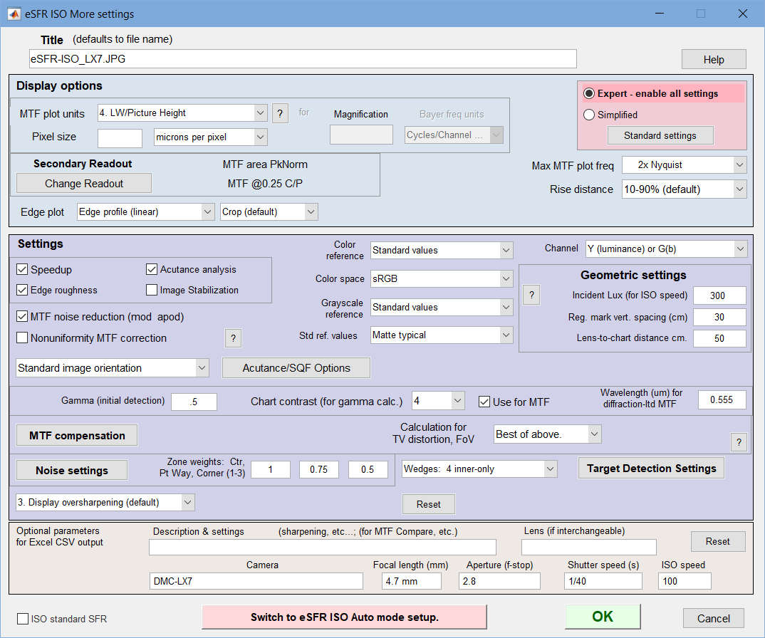
The More settings window, shown below, opens when
- is pressed in the Setup or Rescharts windows.
- Settings, SFRplus (eSFR ISO, SFRreg, or Checkerboard) settings is pressed in the Imatest main window, then is pressed in the Setup window.
The settings are read from imatest.ini, and saved when is pressed. Settings are similar to the settings in the SFR input dialog box.
More settings window
| You can select either Expert or Simplified mode for the settings window. In Simplified mode many settings are grayed out so they can’t be set. If you press , commonly used settings (recommended for beginners) are selected. |
This window is divided into sections: Title and on top, then Display options, Settings, Optional parameters, and finally, or at the bottom.
Title defaults to the input file name. You may leave it unchanged, replace it, or add descriptive information for the camera, lens, converter settings, etc.— as you please.
opens a browser window containing a web page describing the module. The browser window sometimes opens behind other windows; you may need to check if it doesn’t pop right up.
| Display options | (near the top of the window) contains settings that affect the display (units, appearance, etc.). |
| MTF plot units | selects the spatial frequency units for MTF plots and for summary plots. Units are described in the Spatial frequency units section of the Sharpness page Choices include Cycles/pixel (C/P), Cycles/mm (lp/mm), Cycles/inch (lp/in), Line Widths per Picture Height (LW/PH), and Line Pairs per Picture Height (LP/PH). (Note that one cycle is the same as one line pair or two line widths.) If you select Cycles per inch or Cycles/mm, you must enter the Pixel size— either in pixels per inch, pixels per mm, or microns per pixel. For more detail on pixel size, see the box below. |
| Pixel size and units | (Same as pixel pitch for μm/pixel units) Required for cycles per distance (mm, inch), angle, or object distance, but not for C/P, LW/PH, and LP/PH output. Also required for calculating Field of View (FoV) in units of distance (mm, inches). |
| Bayer frequency units |
For Bayer RAW images-only Grayed out for standard demosaiced images.
More detail here. Frequency scaling differs by a factor of two. |
| Maximum MTF plot frequency |
selects the maximum display frequency for MTF plots. The default is 2x Nyquist (1 cycle/pixel). This works well for high quality digital cameras, but not for imaging systems where the edge is spread over several pixels. In such cases, a lower maximum frequency produces a more readable plot. Choices include 1x Nyquist (0.5 c/p), 0.5x Nyquist (0.25 c/p), and 0.2x Nyquist (0.1 c/p). |
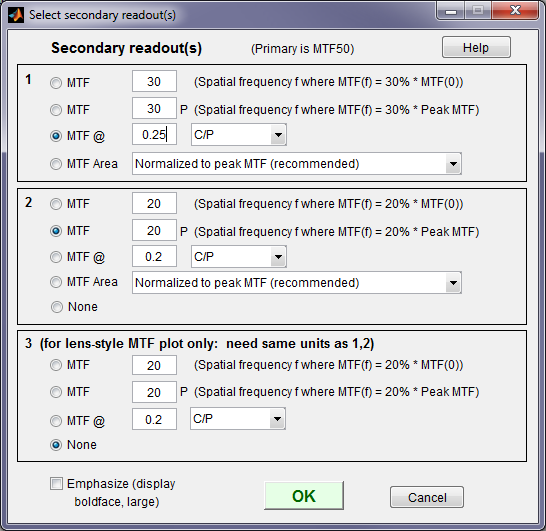
| Secondary readout |
Clicking opens the window shown on the right, which lets you select the readout and save them by pressing .
|
| Edge plot |
selects the contents of the upper (edge) plot. The edge can be cropped (default) or the entire edge can be displayed. Three displays are available.
|
| Lines & arrows |
[Checkerboard-only] Dropdown menu that lest you select (1) No arrows, (2) Display lines & arrows in the corrected image, or (3) Display lines & arrows in both images. Here is an example. |
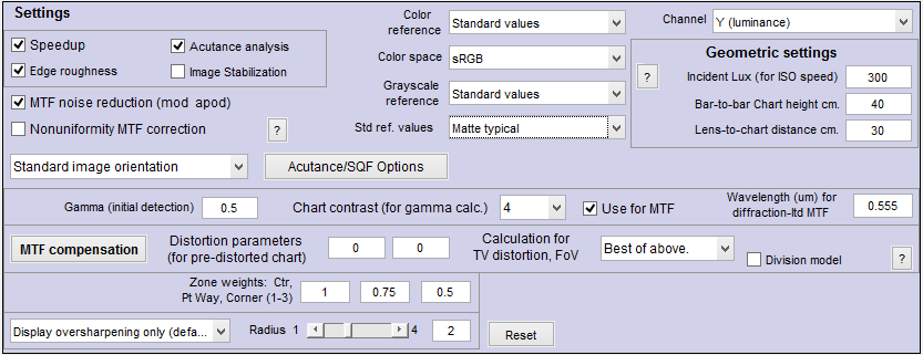
| Settings | (middle of the window) affect the results as well as the display. | ||||||
|
(√) indicates a checkbox. The left column is blank for settings that apply to all modules. [ct] for modules that have tonal and/or color charts (SFRplus, eSFR ISO, and SFRreg with center chart). [s+] for SFRplus, [e] for eSFR ISO, [sr] for SFRreg, and [ch] for Checkerboard. |
|||||||
| Speedup | (√) Speed up calculations by eliminating some calculations that many users don’t require, including noise statistics and histograms. Recommended. Checking Speedup (recommended) can significantly speed up calculations. | ||||||
| Edge roughness | (√) Calculate edge roughness (for including in CSV output). Slows calculations slightly. Required for Edge roughness plot to be displayed. | ||||||
| Acutance analysis | (√) Calculate acutance or SQF. Required for SQF output. Slows calculations slightly. | ||||||
| MTF noise reduction (mod apod) |
(√) Reduce noise using the modified apodization technique. Improves MTF accuracy, especially with noisy images, but not an ISO standard calculation. Generally recommended. | ||||||
| Nonuniformity MTF correction |
(√) corrects MTF for nonuniform illumination perpendicular to the edge. Should normally be unchecked. Described here. | ||||||
| [ct] | Color reference Color space |
used when a color analysis is to be performed (if the image contains the color pattern and the Color chart box is checked in the SFRplus setup window). The Color reference dropdown menu allows you to browse for the reference file, typically a LAB data file in CSV format, supplied with color SFRplus charts. It should be stored in a convenient location. The last selected file is saved. |
|||||
| [ct] | Grayscale reference |
allows you to enter a reference file for the grayscale (tonal response) patches. For Standard values you can choose between Std ref values from target values used to create the print and standard values for several media. | |||||
| Channel | specifies the primary channel to display. All channels are analyzed unless “channel-only” is selected. It’s normally left at it’s default value of Y (luminance), where Y = 0.2125*R + 0.7154*G + 0.0721*B. R, G, and B color channels can also be selected. Selecting one channel-only can significantly speed up calculations (recommended only when speed is critical) and may help in rare instances where bad data in one channel causes a crash. | ||||||
| Image orientation | Selects image orientation for the next run. Options include Standard, Mirror (H-flip), Mirror (V-flip), and Rotate 180 degree. For selections other than Standard, the window background is yellow. | ||||||
| Open the Acutance/SQF settings window, described in Acutance and SQF (Subjective Quality Factor). Acutance is a subjective measure of sharpness that includes viewing conditions. | |||||||
| [ct] | Incident lux | (for ISO sensitivity calculations) When a positive value of incident light level (not blank or zero) in lux is entered in this box, ISO sensitivity is calculated and displayed in the Stepchart noise detail figure. More details are on the ISO Sensitivity and Exposure Index page. | |||||
|
[s+] [e] [ch] |
Bar-to-bar chart height in cm [SFRplus] (right) These are used to calculate the Field of View (FoV) when Pixel spacing (pitch) has been entered. They are optional. For SFRplus the bar-to-bar chart height is measured from the top of the top bar to the bottom of the bottom bar. For pre-distorted charts, use the center distance, as shown on the right. FoV is displayed in Image & Geometry and reported in the CSV and JSON output file if calculated. |
||||||
| Lens-to-chart distance in cm | used to calculate the actual lens focal length when Pixel spacing (pitch) and bar-to-bar chart height have been entered. It is optional. The distance from the lens to target is most conveniently measured with a laser measuring device. Focal length is displayed in Image & Geometry and reported in the CSV output file if calculated. | ||||||
| Gamma |
Gamma is the average slope of log pixel levels as a function of log exposure for light through dark gray tones). It is used to linearize the input data, i.e., to remove the gamma encoding applied by image processing so that MTF can be correctly calculated (using a Fourier transformation, which requires a linear signal). Gamma defaults to 0.5 = 1/2, which is typical of digital camera color spaces, but may be affected by camera or RAW converter settings. Small errors in gamma have little effect on MTF measurements (a 10% error in gamma results in a 2.5% error in MTF50 for a normal contrast target). Gamma should be set to 0.45 or 0.5 when dcraw is used to convert RAW images into sRGB or a gamma=2.2 (Adobe RGB) color space. It is typically around 1 for converted raw images that haven’t had a gamma curve applied. If gamma is set to less than 0.3 or greater than 0.8, the background will be changed to pink to indicate an unusual (possibly erroneous) selection. If the chart contrast is known and is ≤10:1 (medium or low contrast), you can enter the contrast in the Chart contrast (for gamma calc.) box, then check the Use for MTF (√) checkbox. Gamma will be calculated from the chart and displayed in the Edge/MTF plot. If chart contrast is not known you should measure gamma from a grayscale stepchart image. A grayscale is included in SFRplus, eSFR ISO and SFRreg Center ([ct]) charts. Gamma is calculated and displayed in the Tonal Response, Gamma/White Bal plot for these modules. Gamma can also be calculated from any grayscale stepchart by running Color/Tone Interactive, Color/Tone Auto, Colorcheck, or Stepchart. [A nominal value of gamma should be entered, even if the value of gamma derived from the chart (described above) is used to calculate MTF.]
|
||||||
| Wavelength (um) | for diffraction-limited MTF plot. If a number is entered (0.555 um is the default for visible light systems) and pixel spacing is also entered, the diffraction-limited MTF is displayed on the MTF plot and the diffraction-limited edge or Line Spread Function (cross-section of Airy disk) is shown on the edge plot as a faint dashed line – – – – – – –. | ||||||
| lets you to compensate MTF measurements for chart MTF limitations and/or sensor MTF loss (to get closer to lens measurements). Chat compensation requires an MTF compensation file for the specific chart medium. Opens the Chart and sensor MTF compensation window described in detail in Compensating MTF measurements. | |||||||
| [s+] | Distortion parameters | [SFRplus] Two parameters, printed on pre-distorted charts, that allow distortion, hance Fields of View, to be correctly calculated. Works correctly only with SFRplus, but we plan to add it to other modules. | |||||
| Distortion calculation |
Distortion, FoV calculation This dropdown window lets you select the equation for calculating distortion. [Checkerboard] All the calculations shown on the right are available. For the standard multiplication model), odd (2n+1)-order polynomials have the equation, \(r_u = r_d + k_1 r_d^3 + … + k_n r_d^{2n+1} = r_d(1 + k_1r_d^2 + … + k_n r_d^{2n} )\) For the division model (Division model (below) checked), “odd”-order polynomials have the equation, \(r_u = r_d / (1 + k_1 r_d^2 + … + k_n r_d^{2n})\). For both models, all terms (rather than just odd) can be selected for 5th or 7th order polynomials (4th or 6th for Division). We have not seen much advantage for these extra terms. Higher order polynomials (n = 7 and above; 3 or more polynomial coefficients) should be used with extreme care because they can become unstable for Checkerboard grids where the maximum dimension has fewer than n points or where the features are not close to the edge of the image. |
||||||
| Distortion decentering | (√) Calculate center of distortion. Works extremely well (always recommended) with SFRplus and Checkerboard. | ||||||
| Division model | (√) Use the Division model for polynomial distortion, \(r_u = r_d / (1 + k_1 r_d^2 + … + k_n r_d^{2n})\). We have found it to be slightly more accurate than the standard multiplication model for extremely barrel-distorted images. Polynomial exponents are displayed as even numbers, 1 lower than the corresponding term for the standard multiplication model. If checked, the setting is displayed as red with yellow background. | ||||||
| [e] | Settings for calculating noise from the circular grayscale pattern (eSFR ISO-only). Opens the Noise settings window described in Multicharts/Multitest/eSFR ISO Noise. | ||||||
| Zone weights | Weights of the center, part-way, and corner zones. Used for calculating weighted means of key results, displayed in the Multi-ROI and 3D plots. The defaults of 1 (center), 0.75 (part-way), and 0.5 (corners) are for typical pictorial photography; corners should probably be given more weight for technical photography. | ||||||
| [e] | Wedges | [eSFR ISO] Select wedge analysis. None or 4 basic for standard charts (no extra wedges). Additional options are available for charts with extra wedges are 4+4 inner, 4+4+8 corners, 4+4+10 corners. | |||||
| [e] [sr] |
Number of SFRreg targets | [SFRreg, eSFR ISO] For SFRreg, the number of registration mark patterns to search for. For eSFR ISO, the number of SFRreg patterns to be detected and analyzed outside the main eSFR ISO pattern. | |||||
| [e] [sr] |
Minimum SFRreg mark diameter, Maximum SFRreg mark diameter [SFRreg, eSFR ISO] (optional). Can improve detection in complex images. |
||||||
| Standardized sharpening | (Display oversharpening-only is recommended) Standardized sharpening, which displays results as thick red curves and readouts in the edge and MTF plots is not recommended. CSV and JSON summary files are unaffected. See SFR instructions for more details. | ||||||
| Reset | restores the settings in More Settings to their default values. | ||||||
| Additional parameters (all optional) for Excel .CSV output contains a detailed description of the camera, lens, and test conditions. EXIF data is entered, if available, but can be overridden by manual settings. Description & settings is particularly useful for annotating the test system (it is displayed in MTF Compare).These settings are optional but can be useful when several tests are run for different lenses, focal lengths, apertures, or other settings. The settings are displayed next to the MTF plots. They are saved and reused in subsequent runs for files with the same pixel dimensions. If EXIF data is available (currently, only in JPEG files) it overrides the saved settings. The Reset button clears all entries. |
ISO standard SFR If this checkbox is checked, SFR calculations are performed according to the ISO 12233 standard, and the y-axis is labeled SFR (MTF) (ISO standard). This method is slightly less accurate than the normal Imatest calculation, which incorporates a number of refinements, including a better edge detection algorithm and a second-order polynomial fit to the average edge for a more accurate estimate of SFR in the presence of lens distortion. This box is normally left unchecked; it should only be used for comparing normal Imatest calculations to the ISO standard. The difference is typically very small.
When entries are complete, click to return control to the SFRplus setup window or to save settings and return to the Imatest main window. When all entries are complete, click either , , or . saves the settings for use in automated SFRplus runs, which can be initiated from the button in the main Imatest window. saves the settings then calculates results for interactive viewing. A sequence of Calculating… boxes appear to let you know how calculations are proceeding. When calculations are complete, results are displayed interactively in the Rescharts window, as shown below.
Auto mode settings window
Auto mode settings affect plots and output files for Auto runs as well as Imatest IT. These settings do not directly affect interactive (Rescharts) runs. The Auto mode settings window, shown below, opens when
- Auto mode settings is pressed in the Setup window.
- More settings is pressed in the Rescharts window, then Switch to Auto mode setup is pressed in the More settings window.
- Settings (dropdown menu), [SFRplus, eSFR ISO, SFRreg, or Checkerboard] Auto settings is pressed in the Imatest main window.
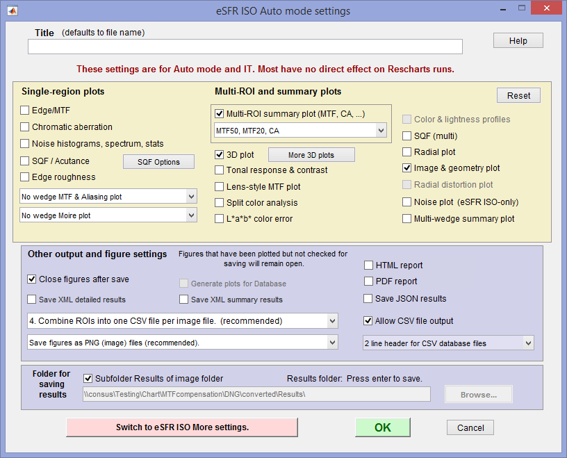 eSFR ISO auto mode settings.
Other modules have different Multi-ROI selections.
The upper box allows you to select single and multi region figures to be plotted and saved in SFRplus auto output. For the most part they are self-explanatory. Note that all figures plotted in Auto mode are saved.
Saved figures, CSV, and JSON files are given names that consist of a root file name (which defaults to the image file name) with a suffix added. Examples:
Canon_17-40_24_f8_C1_1409_YR7_cpp.png
Canon_17-40_24_f8_C1_1409_YR7_MTF.csv
When 3D plot is checked, SFRplus auto plots the last 3D plot displayed in Rescharts unless the button has been pressed and one or more plots has been selected. More 3D plots will be displayed in pink in this case. This allows several 3D plots to be displayed and saved by SFRplus auto.
Close figures after save should be checked if a large number of figures are to be displayed. It prevents a buildup of figures, which can slow processing.
Figures can be saved as PNG or FIG files. PNG files (a losslessly-compressed image file format) are the default— they require the least storage. Matlab FIG files allow the data to be manipulated– Figures can be resized, zoomed, or rotated (3D figures-only), but FIG files should rarely be used because they can be huge. PNG files are preferred if no additional manipulation is required.
A CSV summary file is saved for all runs. An JSON file is saved if Save JSON results is checked. XML is not recommended; it will be deprecated in 2019.
You can select either Save CSV files for individual ROIs or Save summary CSV file only (the summary file is always saved).
Save folder determines where results are stored. It can be set either to subfolder Results of the image folder or to a folder of your choice. Subfolder Results is recommended because it is easy to find if the image folder is known.
Warnings
| A Clipping warning is issued if more than 0.5% of the pixels are clipped (saturated), i.e., if dark pixels reach level 0 or light pixels reach the maximum level (255 for bit depth = 8). This warning is emphasized if over 5% of the pixels are clipped. Clipping reduces the accuracy of SFR results, and severe clipping can render them completely invalid. It makes measured sharpness better than reality. |
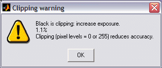 |
|
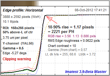
| The percentage of clipped pixels is not a reliable index of the severity of clipping or of MTF measurement error. For example, it is possible to just barely clip a large portion of the image with little loss of accuracy. The plot on the right illustrates strong clipping, indicated by the sharp corner near the “shoulder” on the edge response curve (indicated by the red arrow →). The sharp corner contains significant high frequency energy that exaggerates the MTF measurement, making it better than reality. The absence of a sharp corner indicates that there will be little MTF error. Clipping can usually be avoided with a correct exposure— neither too dark nor light— and by avoiding high contrast targets (like the old ISO-12233:2000 chart). The maximum recommended edge contrast is 10:1. 4:1 contrast (specified in the ISO-12233:2014/2017 standard) is even better. Low-contrast targets are more reliable overall: in addition to better exposure latitude (reduced risk of clipping), they tend to have less sharpening in cameras with nonuniform signal processing, and MTF results are less sensitive to errors in estimating gamma. |
Clipping warnings |
Summary
- SFRplus analyzes images of the SFRplus test chart, ideally framed so that there is white space above and below the horizontal bars in the chart, i.e., so neither bar runs off the top or bottom of the image. The white space should be between 0.5% and 25% of the image height. SFRplus can work without the bars, but distortion and field of view are not calculated. The bars may run off the sides of the image. Interfering patterns (bars, etc.) outside the chart should be kept to a minimum.
- eSFR ISO should be framed to the registration marks are well inside the image. Where possible the entire chart should be inside the image. eSFR ISO has less spatial detail than SFRplus, but has wedges and larger tonal patches that allow much more detailed noise analysis.
- SFRreg is highly flexible, and can include individual charts facing the camera with angular fields of view well over 180 degrees.
- Checkerboard uses a simple checkerboard (chessboard) pattern that works over a wide range of distances: chart framing is not critical.
- Lighting should be even and glare-free. Lighting and alignment recommendations are given in The Imatest test lab.
- The first time any of these modules is run, it should be run through Rescharts. This allows
- parameters to be adjusted and saved for later use in the automatic version, which is opened with a button in the Imatest main window.
- results (listed above) to be examined interactively in the Rescharts window.
- The Auto buttons in the left column of the main Imatest window runs the corresponding module in full automatic mode using settings saved from the most recent Rescharts run. Batches of files can be run.
| Feature | SFRplus |
eSFR ISO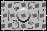 |
SFRreg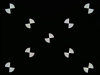 |
Checkerboard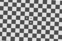 |
| Sharpness map detail | High | Medium | Depends on arrangement | High |
| ISO-standard chart design | – | ♦ | – | – |
| Color analysis | ♦ | ♦ | * | – |
| Tonal response (OECF) | ♦ | ♦ | * | – |
| Noise analysis | Limited | ♦ | * Limited | Limited |
| Distortion | ♦ | Limited | – | ♦ |
| Geometry | ♦ | ♦ | * | ♦ |
| Features and recommended uses |
Imatest’s original automatically-detected chart, in use since 2009. robust and versatile. Some white space recommended above and below top and bottom bars. More spatial and distortion detail than eSFR ISO. |
ISO-standard chart design. Includes wedge analysis. Supports detailed noise analysis. |
Several individual charts are typically placed around the image field. Works with *Available with SFRreg center chart only. |
Relatively insensitive to framing: can zoom in or out as long as distance is large enough so chart quality is not an issue and there are detectable corners. |
♦ denotes strong support; – denotes no support.
Next: Part 3: Slanted edge Results Part 4: Other results
Pixel sizePixel size is closely related to image quality. For very small pixels, noise, dynamic range and low light performance suffer. Pixel size is rarely given in camera spec sheets: it usually takes some math to find it. If the sensor type and the number of horizontal and vertical pixels (H and V) are available, you can find pixel size from the table on the right and the following equations. pixel size in mm = (diagonal in mm) / sqrt( H2 + V2 ) Pixel size in microns (microns per pixel) can be entered directly into the SFR settings box. Example, the cute little 5 megapixel Panasonic Lumix DMC-TZ1 has a 1/2.5 inch sensor and a maximum resolution of 2560x1980 pixels. Guessing that the diagonal is 7 mm, pixel size is 2.1875 (rounded, 2.2) microns.You can find detailed sensor specifications in pages from Sony, Panasonic, and Kodak. |
|


