Stray light (flare) documentation pages
Introduction: Intro to stray light testing and normalized stray light | Outputs from Imatest stray light analysis | History
Background: Examples of stray light | Root Causes | Test overview | Test factors | Test Considerations | Glossary
Calculations: Metric image calculations | Normalization methods | Light source mask methods
Instructions: High-level Imatest analysis instructions (Master and IT) | Computing normalized stray light with Imatest | Motorized Gimbal instructions
Settings: Settings list and INI keys/values | Configuration file input
Table of Contents
- Intro to stray light (flare)
- How to test for stray light
- Setting up for stray light testing
- Imatest’s hardware solution for stray light testing
Intro to Stray Light (Flare)
What is stray light and how is it measured?
Stray light, also known as flare, is any light that reaches the detector (i.e., the image sensor) other than through the designed optical path (definition from IEEE-P2020 pre-release standard). Stray light can be thought of as systematic, scene-dependent optical noise. Depending on the mechanism causing the stray light, it can produce phantom objects within the scene (i.e., ghosts/ghosting), reduce contrast over portions of the image (e.g., veiling glare), and effectually reduce system dynamic range. These factors can adversely affect the application performance of the camera system in a variety of scenarios.
The stray light of a camera can be measured by capturing images of a bright light source positioned at different angles in (or outside of) the camera’s field of view and then processing those captured images into stray light metric images where each pixel in the image is remapped to represent a stray light metric. The light source object itself is excluded, or masked out in the images, as it is not considered to be stray light. Various information and summary statistics can be derived from the resulting stray light metric images.
The primary metric for stray light analysis in version 22.2 of Imatest is Point Source Rejection Ratio (PSRR). The PSRR metric utilizes an on-axis reference image of the light source (specifically, the level within the imaged light source object) to normalize the data of the images under test, providing PSRR stray light metric images as the primary output. PSRR has decades of heritage/use within the aerospace and defense industry as a metric for testing and characterizing the stray light of electro-optical systems for airborne and space applications, including telescopes and satellite imagers.
A GIF of a series of color-mapped stray light metric image plots is one possible output from Imatest 22.2 Stray Light (Flare) analysis. Here, the plotted metric is Point Source Rejection Ratio (PSRR). Each pixel in the input image has been normalized to represent PSRR. The light source object in the image is masked out because it is not stray light. Various stray light artifacts can be seen at different light source positions/angles, including when outside the camera’s field of view. These stray light artifacts are quantified via the PSRR metric scaling of the data.
How to test for Stray Light
Stray light testing requires capturing images of a small, bright light source in a dark room. To build field coverage, the camera can be rotated or the light source can be moved in order to change the angle of the light source with respect to the camera. The captured images are later processed into “normalized stray light” metric images which are the primary output from Imatest 22.2 Stray Light (Flare) analysis.
In summary, to test for stray light, you need:
-
A dark (black) room
-
A small, bright light source
-
A way to rotate the camera under test (or a way to move the light source around the camera under test)
Imatest offers several hardware options to help with stray light testing.

A GIF of a multi-axis sweep of a light source with a camera showing significant “petal flare”. The camera was rotated using the Imatest Motorized Gimbal in order to capture a series of images with the light source positioned at multiple azimuth angles and field angles with respect to the camera, including field angles where the light source is outside the camera’s field of view.
Setting up for Stray Light testing
When rotating a camera or light source for stray light testing, the center-of-rotation should be the front of the camera device under test or the front-most surface of the device that could affect the optical path. For example, if a camera has a lens hood, the camera should be positioned such that the front end of the lens hood is at the center-of-rotation.
The light emanating from the light source should overfill the front of camera device under test, again including any front surface that could affect the optical path. For example, for a phone that has multiple camera modules covered by a protective glass panel, that entire glass panel should be overfilled with light when testing any one of the camera modules, as it’s possible that a stray light path could originate from that surface.
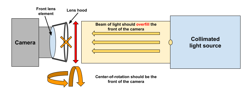
Diagram showing a basic stray light test configuration. The center-of-rotation should be the front of the camera. The beam of light should overfill the front of the camera.
The camera should be well-aligned with the projected beam of light emanating from the light source. The camera may need to translated horizontally and vertically to align it within the center of the beam of light. The camera may also need to be rotated to align the main projection of the light source with the “center” of the image (usually the numeric center) to use as the on-axis position corresponding to a field angle of zero. Rotational alignment can be achieved using a Motorized Gimbal. Translational alignment can be achieved using a Motorized Test Stand.
The Imatest Motorized Gimbal is available in a stray light test configuration where the two axes of rotation are meant to provide control over camera roll and yaw. When set up and aligned properly, this configuration can be used to control the azimuth angle and field angle of a light source with respect to the position of the camera.
The ideal environment for a stray light test is an infinitely large and infinitely dark room in a vacuum.
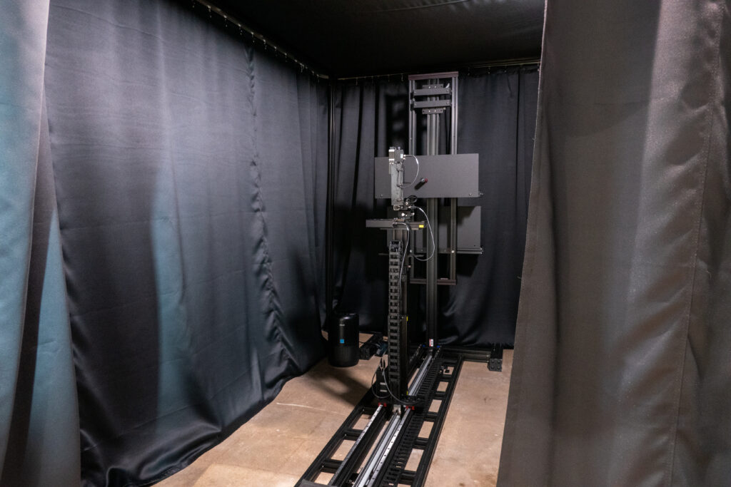
For practical lab testing, it is recommended to use a room with dark/black surfaces. The surfaces of the room may need to be anti-reflective across the full spectrum considered for testing. If the room is not dark to begin with, blackout curtains can be used to effectively darken the environment. The blackout curtains should not immediately surround the setup, but rather, there should be some space between the curtains and the setup (camera and light source) to further prevent unwanted reflections. The larger the enclosure, the better. Additional baffles may be used throughout the setup to further reduce extraneous reflections and ambient light.
Ideally, stray light testing should occur in a dustless environment. Significant dust that is floating within the beam of light may impact the measurement by inducing unwanted reflections and blocking of the light. An air filter can help to achieve a cleaner environment. In addition, a certain level of humidity in the air may help to reduce the amount of floating dust.
Test coverage: extent and sampling
Test coverage should always be considered for stray light testing, regarding both extent (range) and sampling (delta). The principal of test coverage is somewhat analogous to how sharpness (MTF/SFR) can be measured using only the center of an image, but such measurement may not be representative of performance at other locations in the image (e.g., the image corners).
Similarly, the most basic form of the stray light test may involve analysis of a single image of a light source. However, stray light is scene-dependent and therefore, multiple images may need to be tested with the light source positioned at different angles with respect to the camera. This can include images where the light source is positioned outside the camera’s field of view (FoV), as stray light paths can often originate from outside the FoV.
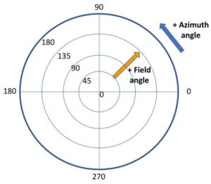
Azimuth angle and field angle represent the position of the light source with respect to the camera. For the purpose of stray light testing, a field angle of zero should coincide with an optical center in image space. For comprehensive testing, it is recommended that the analysis include images where the light source is positioned at field angles beyond the camera’s maximum field of view.
The position or angle of the light source with respect to the camera can be defined by two attributes: field angle and azimuth angle. A stray light “capture plan” can be defined as a series of positions with these two attributes. For stray light analysis in Imatest 22.2, the light source azimuth angle and field angle for each input image can be defined and referenced for analysis via a Configuration file.
An example of a simple stray light capture plan is a single-axis sweep of the light source, wherein the camera is rotated (or the light source moved) such that that the light source covers an arc from the center of the camera’s FoV to somewhere outside the FoV, with equally spaced rotation increments. This capture plan effectively tests multiple field angles at a single azimuth angle. Another option would be to perform a single-axis sweep across the full FoV, for example, covering a 180 degree arc in front of the camera. Field angle increments of 1 degree or less may be necessary for comprehensive stray light testing, depending on the FoV of the camera.
Another example of a stray light capture plan is a multi-axis sweep of the light source, wherein the camera is rotated (or the light source moved) to perform multiple single-axis sweeps at several azimuth angles. For example, a valid capture plan could be to test at field angles from 0 to 90 degrees, with 0.1-degree increments, at azimuth angles corresponding to horizontal, vertical, and two diagonals, where the diagonal angles intersect with the corners of the image.
Single-axis sweeps assume radial symmetry. Certain stray light paths caused by dust, lens surface defects, or other asymmetries may not be caught so, for comprehensive testing, it may be necessary to test for stray light at multiple azimuth angles. Both single-axis and multi-axis sweeps can be can be performed with the Imatest Motorized Gimbal.

A GIF of a series of stray light images captured from a monochrome near-infrared camera paired with a C-mount fisheye lens (FoV >180 degrees). The camera was rotated using the Imatest Motorized Gimbal. These images show a 220-degree horizontal sweep of an infrared collimated light source using field angle increments of 1 degree. Diffraction spikes can be seen immediately surrounding the main light source projection (these may be categorized as stray light). Some stray light artifacts only appear at specific light source angles.
Ideally, linear image data should be used to test for stray light. Some metrics, like Point Source Rejection Ratio (PSRR) assume linear input data. Certain image signal processing (ISP), especially those affecting linearity (e.g., gamma correction), can and will impact stray light measurements. Nevertheless, processed images may be analyzed as well, since it can be valuable to see how the ISP may impact the perceived stray light.
Imatest 22.2 stray light analysis supports input image files containing monochrome or 3-channel (e.g., RGB) image data. Unformatted raw images are also supported with use of Read Raw settings.
Imatest’s hardware solution for Stray Light testing
Imatest offers several hardware products to use for stray light testing. Some key hardware components include:
-
Imatest Motorized Gimbal (stray light test configuration)
-
Broadband Halogen Fiber Optic Illuminator (benchtop setup)
-
Imatest configurable stray light source (in development)
-
Imatest Motorized Test Stand (in development)
- Imatest Blackout Curtain Fixture
The Imatest Motorized Gimbal allows for programmatic control over camera roll and yaw (or alternatively, pitch and yaw) which effectively provides control over the field angle and azimuth angle of a light source when properly set up and aligned. The Motorized Gimbal has 360-degree range for both axes and positional accuracy of 0.08 degrees. The Motorized Gimbal comes with a goniometer to help with leveling and alignment. The Imatest Motorized Gimbal is available on the Imatest Store. See the Motorized Gimbal instructions page for additional details on how to get started with using the gimbal for stray light testing.
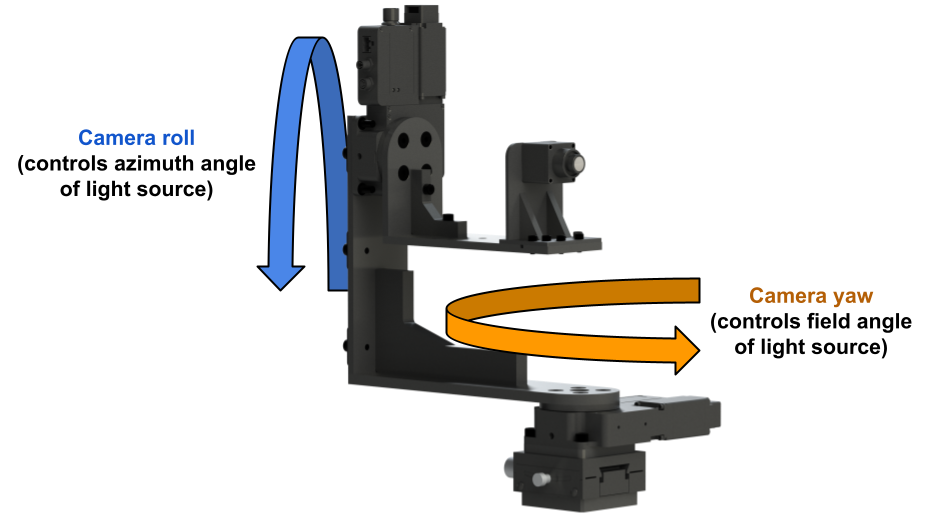
A render of the Imatest Motorized Gimbal with an automotive-grade camera (and custom camera holder) mounted in the stray light test configuration. In this configuration, the gimbal allows for control over camera roll and yaw, effectively providing control over the field angle and azimuth angle of a light source when properly set up and aligned.
Broadband Halogen Fiber Optic Illuminator (Benchtop Setup)
The Broadband Halogen Fiber Optic Illuminator is a multi-purpose light source that is usable for basic stray light testing. The halogen bulb covers both the visible and near-infrared spectrum. The fiber is easy to maneuver for simple and flexible lab setup. The fiber is paired with a collimation optic that focuses the light into a narrower beam, though still diverging. The fiber is mounted to a two-axis goniometer, useful for camera-to-source alignment. An extended, diverging light source such as this can be used for repeatable stray light testing so long as the setup (e.g., camera-to-source distance and alignment) remains constant. A benchtop stray light test fixture, including the Broadband Halogen Fiber Optic Illuminator and the Motorized Gimbal, is available on the Imatest Store.
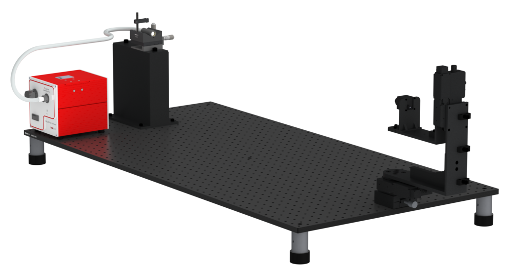
A render of a stray light test setup including the Broadband Halogen Fiber Optic Illuminator. The light source and Motorized Gimbal are mounted to a metric optical breadboard. A collimation optic is attached to the fiber to focus the light into narrower beam, though still diverging. The optic is mounted to a two-axis goniometer to aid with camera-to-source alignment. A light shield (not pictured) is placed in front of the light source to block extraneous light from the source.
Imatest configurable stray light source
Imatest is developing a configurable light source designed for stray light testing. The design includes a 4” integrating sphere with a radiance monitor detector for highly uniform and controlled output. Attached to the integrating sphere are three ports for swappable LED engines. For example, LED engines corresponding to 5000K visible light, 850nm, and 940nm near-infrared light could be used to test for stray light in both the visible and near-infrared spectrum (other wavelengths are available). The integrating sphere acts as a diffusor that effectively blends the light from the separate LED engines into one uniform light source. The light source may include adjustable optics allowing for configurable divergence of the output beam (up to collimation), as well as an adjustable iris allowing for configurable source object size. A collimated, spatially uniform beam of light allows for controlled and repeatable stray light testing. This hardware component is still in development and is estimated to be ready in Q1 2023.
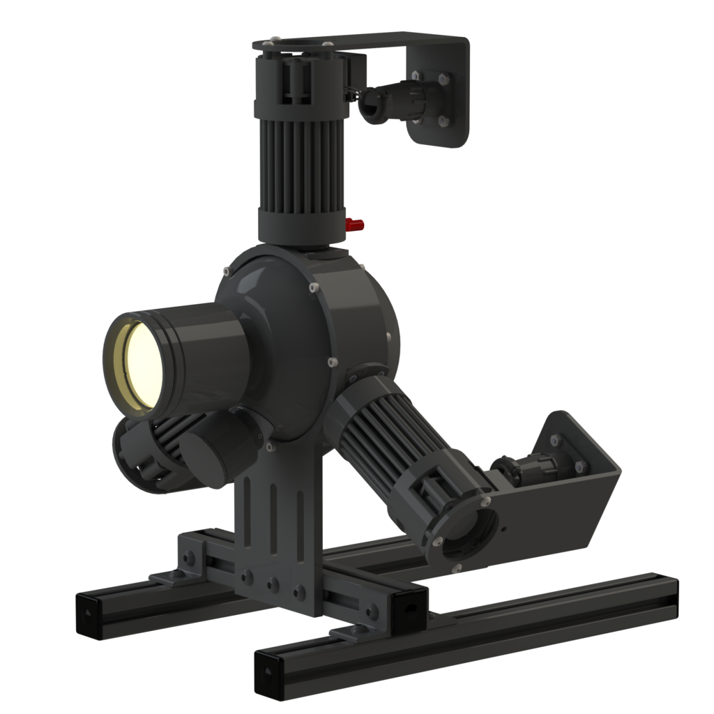
A concept render of the Imatest configurable light source designed for stray light testing. The design includes adjustable optics attached to an integrating sphere with a radiance monitor detector and three swappable LED engines.
Almost any light source can be used to test for stray light. Even a simple flashlight may work in some cases. However, certain characteristics of the light source will effect a stray light measurement as well as the repeatability of the measurement. These characteristics include the intensity/brightness, spectrum, temporal and spatial uniformity, collimation or divergence, and angular extent. The Imatest light source has been designed with these factors in mind.
Regardless of the light source being used, the camera under test needs to be well-aligned to achieve good repeatability in the measurement. Imatest is developing a Motorized Test Stand that can be used for a variety of automated image quality testing purposes, including stray light testing. The Motorized Test Stand provides three axes of automated translational movement with sub-millimeter precision. The Motorized Test Stand comes with a test chart holder that can be used to mount other targets and equipment, such as a light source for stray light testing. When paired with a Motorized Gimbal and light source, the Motorized Test Stand can significantly aid with set up, camera-to-source alignment, and automated testing. This hardware component is still in development and is expected to be ready in 2023.
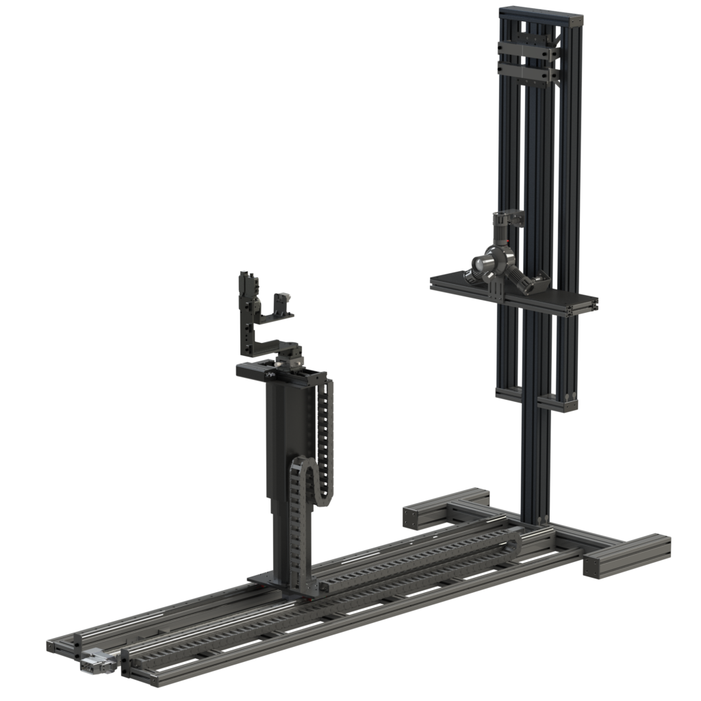
A concept render of the Imatest Motorized Test Stand paired with the Motorized Gimbal and configurable light source for stray light testing. The Motorized Test Stand provides three axes of translation which can aid in set up, camera-to-source alignment, and testing, along with variety of other image quality testing applications.
Imatest Blackout Curtain Fixture
For stray light testing in a lab, it is recommended to use a room with dark/black surfaces. However, if the room is not dark to begin with, blackout curtains can be used to effectively darken the environment. The blackout curtains should not immediately surround the setup, but rather, there should be some space between the curtains and the setup (camera and light source) to further prevent unwanted reflections. The larger the enclosure, the better. Imatest offers a Blackout Curtain Fixture to help reduce the amount reflections from the test environment. The Imatest Blackout Curtain Fixture may be offered in different sizes and will be available in Q1 2023.


